Types of Transmitters
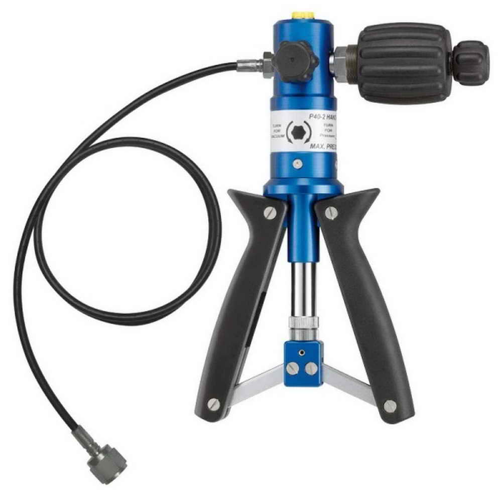
July 11, 2017Hand Pressure Pump / Manual Pressure Calibrator
July 16, 2017
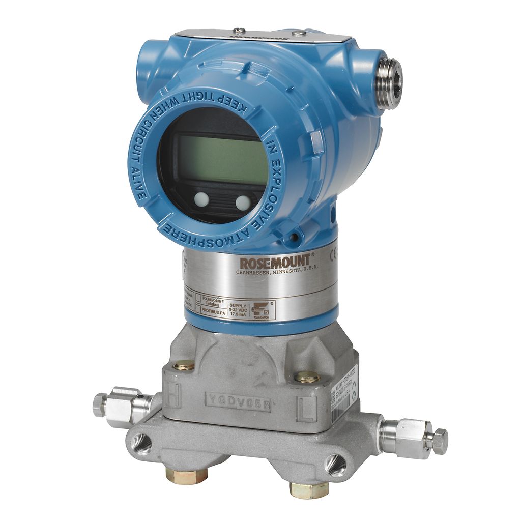
Pressure Transmitter
Series 3051 Transmitters
These multifunctional transmitters can be used to measure various variables such as pressure, flow, level, and differential pressure.
The supply voltage for these transmitters is 24V, and their output is 4 to 20 mA. These transmitters are SMART, meaning they can be programmed or calibrated for specific measurements using HART.
These transmitters are composed of various components.
Sensor Section
It consists of two capsules. One side of these capsules is in contact with the substance whose pressure is to be measured, and the other side is in contact with a piezoelectric sensor. The capsules contain oil. When pressure is applied, it is transmitted to the piezoelectric resistor, changing its resistance. This resistor is part of a Wheatstone bridge circuit, and thus the pressure is measured and converted into a 4–20 mA current.
Electronics Board (Module)
This part converts the sensed changes into 4–20 mA electrical signals. It is also responsible for storing data entered into the transmitter, data retention and transmission, and managing the LCD attached to the transmitter.
Electrical Connections Section
This section includes two terminals labeled + and – for supplying power to the transmitter and transferring data. A third terminal, labeled TEST, is used by connecting an ammeter between – and TEST to read the transmitter’s current.
Display Section
Responsible for displaying information.
Manual Zero and SPAN Buttons
A half-plate is located on top of the transmitter. By loosening its screw, the plate rotates aside, revealing two buttons used to manually set Zero and SPAN on the transmitter.
Transmitter Adjustment via Zero and SPAN Buttons
Disconnect the transmitter from service. Press and hold the Zero button for five seconds until “Zero” appears on the LCD. Reconnect the transmitter to the process and apply the maximum pressure. Then, press and hold the SPAN button for five seconds until “SPAN” appears on the LCD. After that, close the half-plate and return the transmitter to service. This method is rarely used; HART is preferred for calibration.
Jumpers
Located on the module or LCD, they are used for alarm settings, i.e., to define high or low alarm thresholds. The second jumper is for write protection to safeguard the software.
As mentioned, this is a multi-purpose transmitter that can be used for measuring level, pressure, flow, and differential pressure. The usage varies for each application.
3051 for Pressure Measurement
For pressure measurement, the 3051 model has a single capsule input. The material whose pressure is to be measured is connected directly via a line. It’s important to ensure the temperature and corrosiveness of the substance do not exceed specified limits, and that a pressure transmitter matching the line’s pressure range is used. The pressure unit is defined via HART. A manifold must always be used with these transmitters. For liquid measurements, the device should be installed below the liquid level; for gases, the transmitter should be installed above to prevent gas condensation in the capsules. The transmitter should be mounted on a stable, vibration-free base.
Transmitter connections must be tight and leak-free. Avoid replacing factory fittings. The device should be installed away from corrosive materials and high temperatures, as heat can interfere with its function.
3051 for Flow Measurement:
Flow refers to the amount of material passing through a specific cross-section over a given period.
For flow measurement using the 3051 pressure transmitter, differential pressure methods are applied.
Devices used to create differential pressure in a line include Venturi, Orifice, Flow Nozzle, and Pitot Tube. These devices generate pressure differences, which are sent to the transmitter’s capsules. Flow is calculated from the square root of the differential pressure.
Methods of Creating Differential Pressure
Using Orifice:
In this method, the orifice is installed in the line based on the material type. Pressure is transmitted to the pressure transmitter from before and after the orifice using tubes — to LegH and then the output (based on flow direction) to LegL.
The transmitter must be set to Sqroot mode. In this case, a square root symbol appears on the LCD.
How to Use the Orifice:
Based on the orifice design, which has a hole in the center for liquids, on top for gases, and at the bottom for semi-solids or slurry (to avoid sedimentation), it is installed in the flow path. The narrow side is the inlet and the wider side is the outlet.
Using Venturi:
A device used to create differential pressure in the line. It functions like an orifice, and both input and output legs are connected
3051 for Level Measurement (LT)
In this method, differential pressure is also used. The transmitter is installed at the bottom of the tank on a suitable mounting base, as shown in the figure. In this case, the transmitter must be configured in Linear mode because the relationship between level and pressure is linear.
The transmitter legs must be filled with oil. The transmitter calibration point (LRV) should be set at the negative cement base level if there is a level difference to compensate for the height of the cement base. In this method, the specific gravity of the liquid inside the tank must match that of the oil. One of the reasons for using oil is to prevent corrosion of the materials inside the tank or the condensation of gas inside the tank into liquid in the legs. Essentially, the oil isolates the transmitter from the tank's contents.
3051 for Differential Pressure Measurement (DPT)
This method is used to measure the pressure between two points. The transmitter must be set to Linear mode.
Manifold
In general, a manifold must be installed for the 3051 pressure transmitter in any application to allow the pressure transmitter to be taken out of service when necessary. The manifold isolates the two capsules from each other.
Below are some explanations about the manifold.
The manifold has two input legs and a vent leg. Normally, the valves are open to each other, but when the equalizer valve is closed, legs A and B are separated, and each directs the process fluid toward its capsule. Sometimes, due to clogging or liquid accumulation (in case of gas) on the capsules, the transmitter may produce errors.
ترانسمیترهای اختلاف فشار , ترانسمیتر فشار, تعریف ترانسمیتر فشار, ساختمان ترانسمیتر فشار, سنسور فشار ترانسمیتر, طرز کار ترانسمیتر اختلاف فشار,