Piping and Instrumentation Diaphragm (P&ID)
Review and Comparison of Orifice and Venturi Flow Meters
June 28, 2020
Positioner
August 24, 2020Piping and Instrumentation Diagram (P&ID)
The production of chemical products results from processes carried out under specific conditions such as temperature, pressure, pH, and more. These chemical processes take place within the physical framework of pipes, tanks, drums, valves, heat exchangers, pumps, boilers, and other equipment, and the measurement of process variables is performed using connected instrumentation devices. P&ID diagrams are used to illustrate how and where this equipment is installed and the relationships between them.
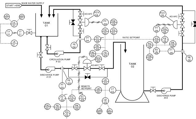
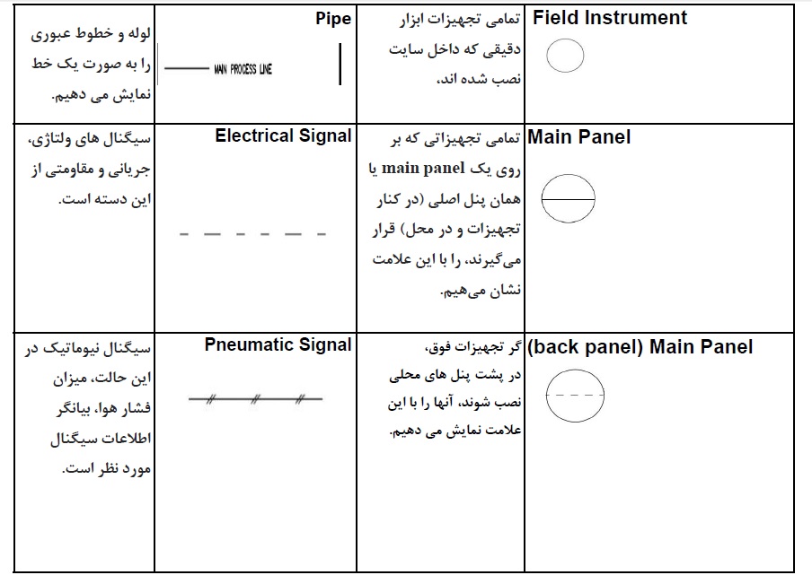
In these diagrams, the piping routes are represented by straight lines, and instrumentation equipment is depicted as circular symbols. Dashed lines indicate electrical signals, while pneumatic signals are shown as lines with two short perpendicular marks.
P&ID diagrams are prepared by chemical and process engineers and then provided to control engineers. Piping and instrumentation diagrams are important engineering documents in a project and are frequently referred to during operation, maintenance, and development phases. In complex, multi-stage industrial processes, having P&ID diagrams is essential for overhaul and troubleshooting, helping to prevent potential errors.
Instrumentation devices are generally connected to the measurement points in two ways: Direct and Remote. In the Direct configuration, these devices are connected directly to the line using threads or flanges. In the Remote configuration, the fluid is diverted from the line through a tube before being connected to the measurement instruments.
Company Isatis Farayand Abzar ready to supply instrumentation devices, accessories, and related fittings, available for immediate and customized delivery.
To view the products Click here to download the NuovaFima product catalog.