Positioner
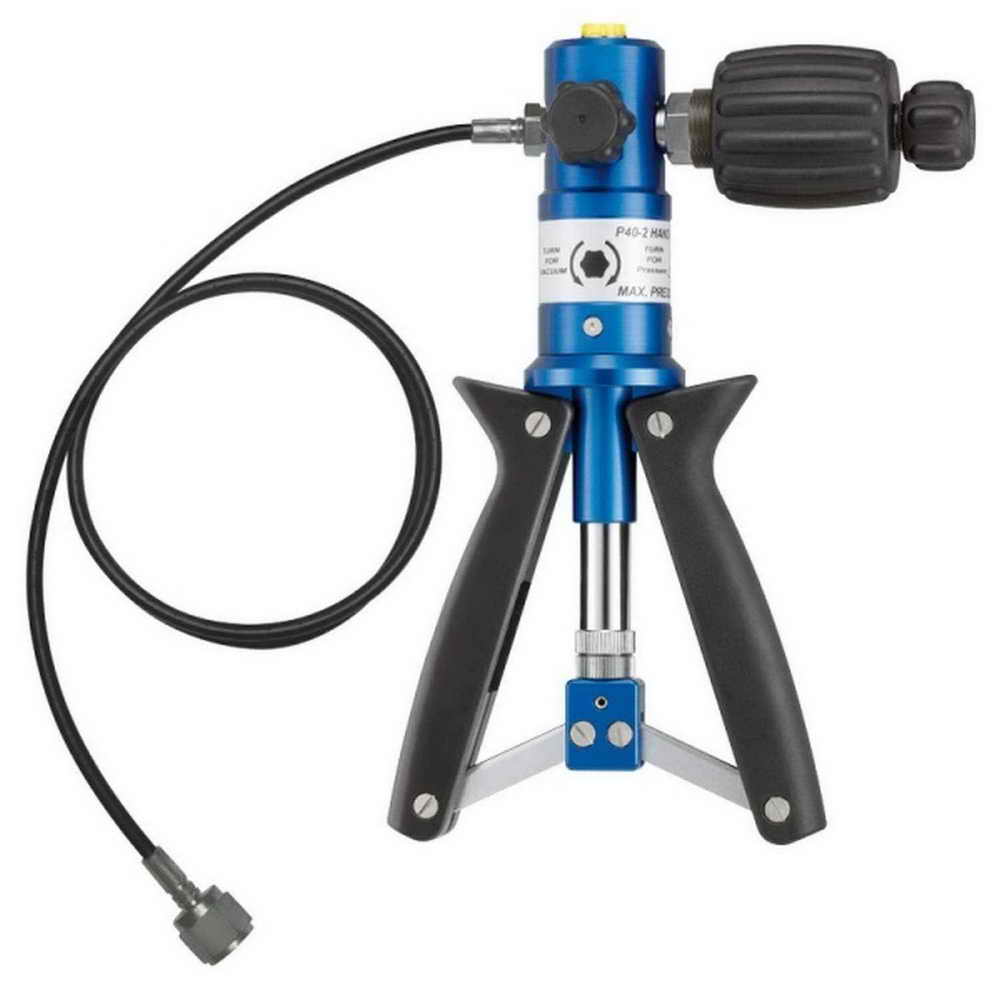
Hand Pressure Pump / Manual Pressure Calibrator
July 16, 2017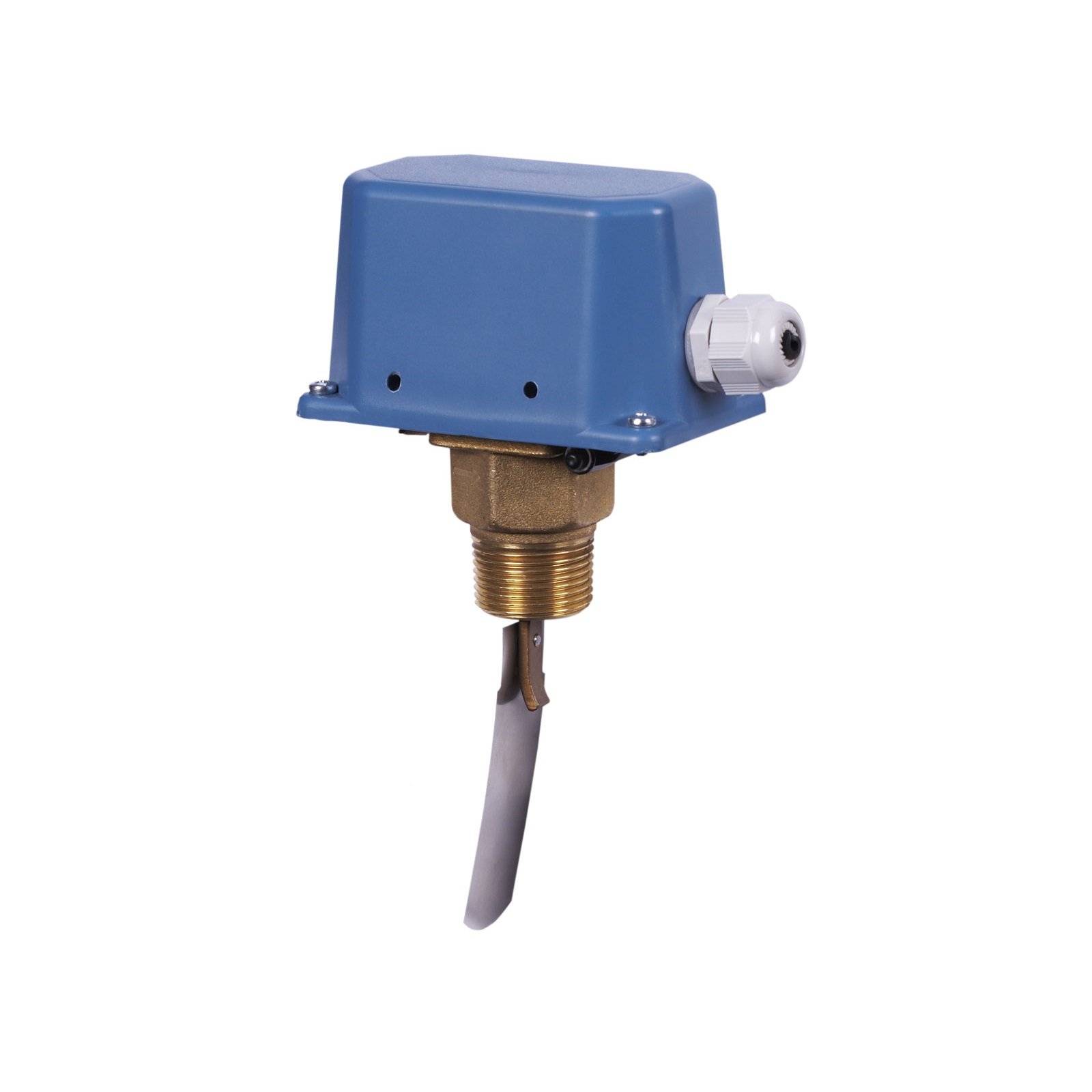
Pedal flow switch
September 3, 2017
(Positioner)
For precise control of a control valve and quick response to changes in the electrical signal, a device called a positioner is required on valves. Positioners can be mechanical, pneumatic, or electric, and they increase the pulse transfer speed (3 to 15 psi). Based on the feedback received from the valve position, the positioner is responsible for controlling the valve.
The positioner amplifies the signal sent from the controller and transmits it to the actuator. It also eliminates any discrepancy between the actual valve position and the position commanded by the controller, ensuring the valve reaches the correct commanded position.
A positioner is required in some actuators to make the actuator compatible with the instrumentation pressure signal or to provide specific operational stability.
The positioner includes a set pressure, a supply pressure, and an output pressure. The output pressure from the I/P (current-to-pneumatic signal converter) serves as the set pressure for the positioner.
Components of a Positioner (Positioner Components)
The positioner consists of components such as the bellows or spool valve, which receives the signal from the controller; the link or balance rod, which compares the received signal with the changed position of the valve stem; the power valve, also known as a relay or booster, which amplifies the signal from the controller; and the cam, which defines the relationship between the control valve plug position and the controller’s signal.

The signal from the controller causes movement of the bellows, and any pressure imbalance changes the distance between the flopper and the nozzle. As a result, the pressure on the output relay diaphragm changes, which in turn alters the relay output pressure, correcting the valve position. This compensation, however, is only possible for up to 20% deviation from the actual position.
When using a positioner, attention should be paid to factors such as: 1) high turbulence forces caused by large valve sizes, high pressure drops, or a combination of both; 2) long transmission lines between the controller and the control valve, which can result in a time lag; 3) viscous (viscous) fluids, solid-bearing fluids, or fluids that tend to close the valve; 4) high pressure requiring unusually tight packing to prevent stem leakage.
1- Pneumatic Positioners (Pneumatic Positioner)
The signal used in this type of positioner is typically 3–15 PSIG. This positioner uses the main air line for supply, and based on the pneumatic signal received from the controller, it sends the necessary command to the actuator to open or close the valve.
2 – Current-to-Pneumatic and Pneumatic-to-Current Positioners (I/P):
In this type of positioner, the electrical signal from the controller is used to actuate the device, and the corresponding output air is applied to the valve actuator. .
3 – Smart or Digital Positioners (Digital Positioner):
These positioners operate similarly to the previous type, with the difference that instead of using a 4–20 mA signal for actuation, they use digital signals. These signals are sent digitally and encoded from the controller to the positioner, which then applies the output air to the actuator according to the received logic. The signal type may use protocols such as HART or FIELDBUS. For example, if the controller’s output signal is HART, the positioner must support this protocol. If a conventional (analog) positioner is used, appropriate interfaces are required between the controller and positioner to convert the signal.