
Tank Level Control Using Pressure Switch Gauges

Positioner
August 24, 2020
Tank Level Monitoring and Control Using Capillary Pressure Transmitters
October 19, 2020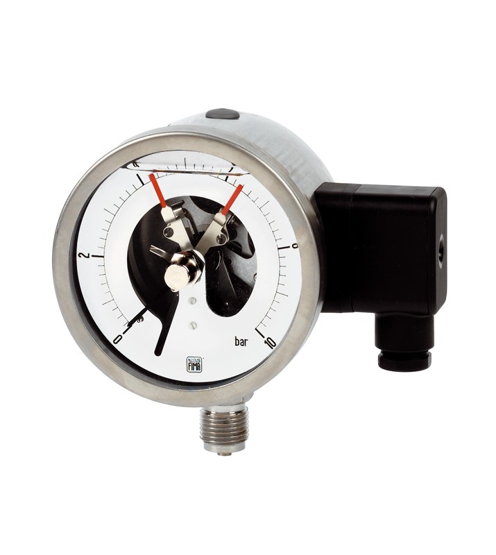
Tank Level Control Using Pressure Switch Gauges
Fluid level measurement (Level Measurement) is of great importance in all industries. If this task relies on manual monitoring, it not only imposes continuous costs on the employer but also increases the likelihood of measurement errors or improper actions. An increase in the fluid level in a tank may lead to product overflow, damage to pressurized tanks, and safety hazards.
A decrease in the fluid level in tanks can also cause damage to pipeline equipment and failure of electric pumps due to running dry or under no-load conditions. Measuring tank levels with instrumentation equipment helps to reduce costs, optimize processes, increase speed, and enhance system reliability.
Measurement using hydrostatic pressure caused by fluid height is one of the common methods in industry. There are various instruments available for pressure measurement in industrial instrumentation, and in this article, we aim to
In this method, the U.R.V (Upper Range Value) and L.R.V (Lower Range Value) are first calculated based on the maximum H max and H minimum min and the required range of the pressure switch gauge is determined. To control both the minimum and maximum fluid levels in the tank, a pressure switch gauge with two contacts should be used.
In this case, based on the minimum and maximum fluid heights and the resulting pressures, the set point locations are determined. Next, the set point needles are adjusted to the desired high and low values using the wrench provided in the gauge box. The pressure switch gauge is then connected to the tank via a fitting at the bottom of the tank.
In this setup, two switches (Low and High) can be used for automation and appropriate actions in the control circuit. Additionally, depending on the position of the pointer, the fluid level at any moment can be continuously and directly read from the gauge dial.

